Interfacing with an LTC1609 ADC
Datasheet. Link accurate as of this post being published.
Introduction
The LTC1609 from Analog Devices is a neat little SAR ADC, with 16 bits of resolution across a unipolar or bipolar 10V, 5V, or 3.3V, 200 ksps sample rate, and a decent SNR at 87 dB.
The unipolar 10 V resolution is actually rather unique amongst all the ADCs I looked at, and was the selling point in my choice of this ADC.
This chip only comes in SSOP or SO packages which precludes it from being easily used with Arduino’s on a breadboard.
The chip uses a SPI-like protocol to clock out the results of its last conversion. I say SPI-like because it has a number of quirks that prevent it from being used with a microcontroller’s hardware SPI out of the box.
I’m sharing my implmentation of interfacing the LTC1609 with an Arduino using the built in SPI library, in the hope that it saves time for someone out there.
If you are bit banging the SPI protocol, then this post will nto be of much use to you.
Setup
In my case I was using an Arduino to interface with this chip. As such, I will be assuming that you have a hardware SPI clock and a 16 MHHz core clock.
The LTC1609 will be used in the “External Discontinuous Data Clock Data Read After the Conversion”. This mode was selected as the datasheet claims that it provides the best performance.
This mode and below code is valid no matter that voltage range the ADC is configured to.

This mode requires 17 clock cycles to fully clock out the 16 bit conversion result. The extra clock cycle is used to generate a pulse on SYNC, after which data is clocked out.
This doesn’t play well with provided SPI libraries, as SYNC is only pulsed when the clock starts, and clocks start only when an 8 bit transfer is initiated.
Implementation
uint16_t adcReadHardware()
{
	// Bring RC down to indicate to ADC start conversion
	// Each port write will take approximately one cycle
	// Thus the pin will be driven low for at least 62.5 ns, longer than
	// required minimum of 40 ns
	// And much shorter than required maximum of 1.2 us

	// digitalWrite(adcRc, LOW);
	// digitalWrite(adcRc, HIGH);
	PORTL &= ~(1 << PORTL1);
	PORTL |= 1 << PORTL1;

	// while (!digitalRead(adcBusyPin))
	// {
	// 	// ADC is busy for 2.64 us
	// }
	while (!(PINL & B00001000))
	{
		// Busy wait loop, new check is made approximately every cycle (63ns)
		// ADC will return with result in 2.64 us (measured with scope)
	}

	// 16 bits of data will be transferred. However, first two received bits
	// indicate SYNC, and need to be discarded.
	// Therefore we make three transfers and do some shifting
	// XX|||||| |||||||| ||XXXXXX
	//		X indicated useless bits
	//		| indicates useful bits
	uint8_t adcTransfer1 = SPI.transfer(0xFF);
	uint8_t adcTransfer2 = SPI.transfer(0xFF);
	uint8_t adcTransfer3 = SPI.transfer(0xFF);

	adcTransfer1 <<= 2;
	adcTransfer1 |= adcTransfer2 >> 6;

	adcTransfer2 <<= 2;
	adcTransfer2 |= adcTransfer3 >> 6;

	return ((adcTransfer1 << 8) | adcTransfer2);
}
First bring the ADC’s RC pin LOW to indicate the start of a conversion. I used port manipulations for speed, but digitalWrite() should be fast enough to get it in under the 1.2 uS stipulated in the datasheet.
Next is a busy wait loop checking if ADC BUSY has been pulled HIGH, to indicate that a conversion is ready to clock out. Again I used port manipulations for speed, but digitalRead() is perfectly adequate if you’re not pressed for speed.
Now for the actual conversion results. The Arduino in its default SPI settings, will capture data on rising edges, therefore the two leading bits are SYNC. The Arduino captures 16 bits of data, and with some bit shifting we return a correct 16 bit conversion result.
Notes
Arduino requires SPI.transfer() to be passed a parameter, so the 0xFF are dummy values. SPI MOSI is not even connected to the ADC.
Bit banging and port manipulation for the SPI transfer section can reduce the number of excess bits captured, but I didn’t see the payoff to be worth it at the time of implementing, and can be an exercise for the reader.
Memory can be saved by doing the bit shifting during the SPI transfer, and reusing one of the adcTransfer variables.
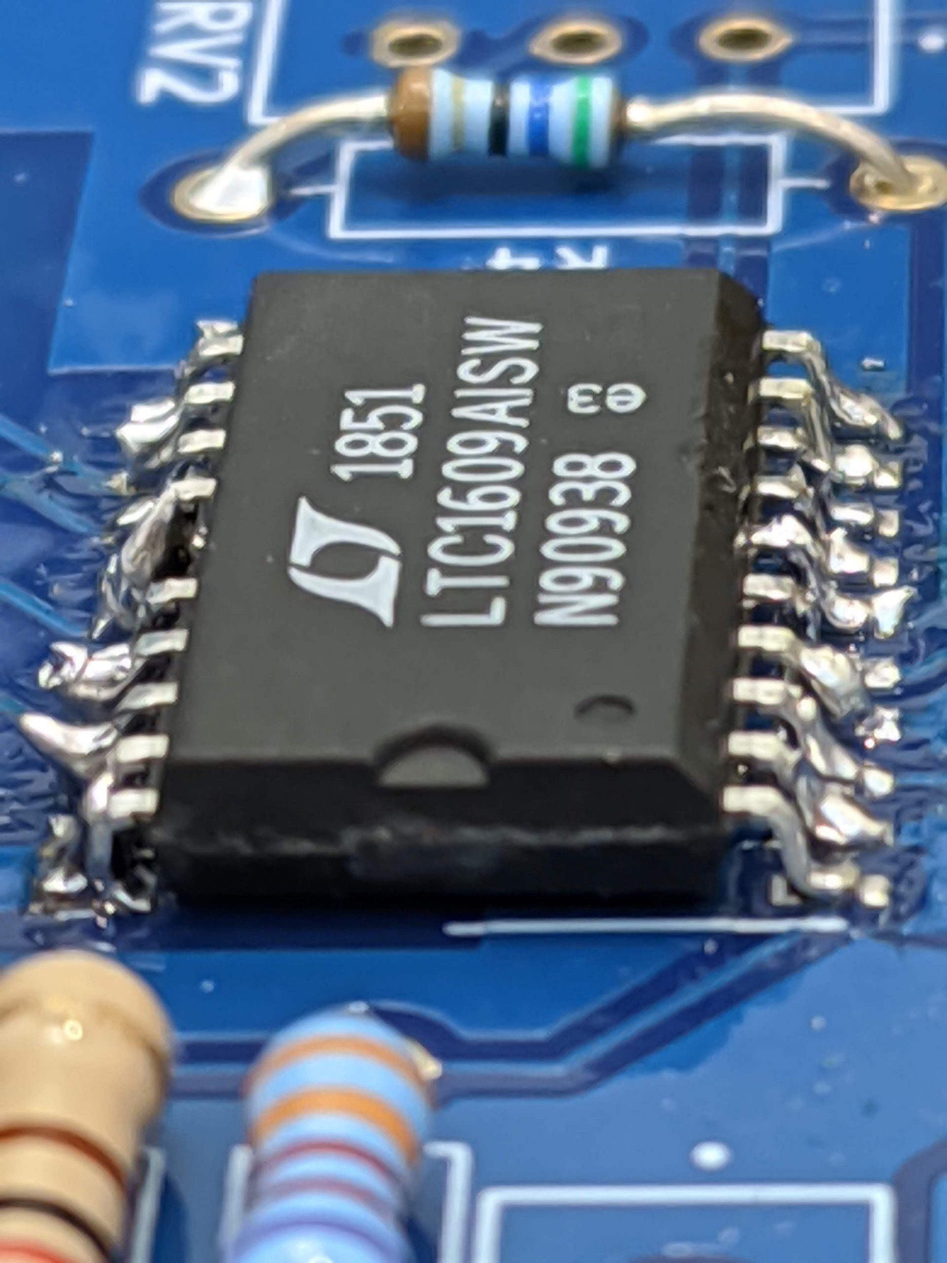
The LTC 1609 in the featured image above was soldered by me, and indeed the soldering is awful. My excuse is that I did not have access to a reflow station and I needed the ADC workign ASAP.